
by Syeda Mehjabin
The work was done under the supervision of Dr. Yun Ye. The author would like to acknowledge the support from the CUNY Research Scholars Program (CRSP).
ABOUT THE AUTHOR
Syeda is an Environmental Engineering student here at LaGuardia, her plan after graduating with her associates is to continue pursuing her bachelor's at a four-year CUNY university. She is currently supported by CUNY Research Scholars Program working on improving wireless communications within underwater environment, under the supervision of Dr. Yun Ye. Other than attending LaGuardia, Syeda likes to spend her free time exploring state parks and staying active.
This paper introduces signal modulation and its application in acoustic wireless underwater communication. Modulation is closely related to error correction coding which is used to reduce issues with transmission of data in noisy or resistant environments, such as the ocean. This paper will describe the basics of underwater communication, the issues this technology encounters and describe solutions conducted by other researchers.
Humanity has already made many advances above ground with wireless communication and new discoveries that stretch far from our planet using this technology. However, we know less about our planet's hydrosphere (ocean) than we think, even when we know the ocean covers 70% of our planet [1]. Implementing wireless communication underwater will allow us to receive better data from autonomous robotic communication, monitor the environment, and discover new scientific exploration underwater [2]. However, there are a number of disturbances in the oceanic environment that make it very difficult to approach wireless communication the same way as we do above land. Different approaches must be made in order for a signal to perform successfully underwater. A few disturbances are limited bandwidth, multiple signal paths underwater and ambient noise from the ocean's ecosystem.
To understand wireless communication in the ocean, we must first learn a bit about wireless communication above ground. Communication is the exchange of data between two bodies, this takes place between a transmitter and receiver. A sender encodes a message in the transmission process and the receiver is responsible for decoding this message properly. In wireless communication the messages are in binary digital numbers of zeros and ones which relate to sinusoidal waves. Wireless communication is very common, all around our environment through wi-fi, remotes and cell phones. Above ground, wireless signal is transmitted by the modulation of electromagnetic waves. This is not efficient in the sea because the ocean is a different medium compared to above land. However, an alternative is mechanical waves which are commonly known as acoustic waves.
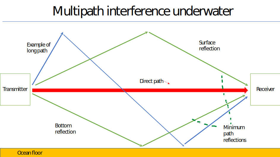
Figure 1. Multipath interference in underwater communications [1].
Many researchers have acknowledged the numerous issues in underwater wireless communication and have conducted experiments to contribute solutions. Yuri Labrador and his research team at Florida International University have found some error coding corrections within the ocean environment [1]. Error Correction Coding (ECC) is used to prevent errors in the flow of data through boisterous environments such as the ocean where many noises can disrupt the correct data from being transmitted. An issue they faced was that the acoustic signal encountered multiple paths from the reflections created by the bottom ocean surface and top sea surface, as shown in Figure 1. Labrador's team implemented turbo codes to resolve this issue. Turbo codes are a form of error correction codes which are high-performance codes that prevent noise interference. ECC needs to be implemented with consideration of signal modulation, because as shown in Figure 1, the signal will face noise interference in the medium that it is traveling within. To explain this concept, the three types of modulations that will be discussed are Quadratic Amplitude Modulation (QAM), Phase Shift Keying (PSK), and Frequency Shift Keying (FSK).
Signal transmission in the wireless channel includes several steps [3]. Figure 2 illustrates the signal transmission process in the wireless communication system. Information is first sent as an analogue wave to the transmitter, from there the signal travels to the source encoder then channel encoder and then then it is turned into data using modulation. After modulation, the data travels through a channel. The signal is then demodulated, sent to the channel decoder and then to the source decoder. However, as the illustration suggest, noise interference in the channel can create a switch in binary data, this will create an error where the transmitter and receiver will have different messages [3]. This issue can be resolved by error coding from the modulation. Modulation is to manipulate the parameters related to the wave form for the signal. A signal is sent in the form of sinusoidal waves that have one of the three parameters changed in the equation below:
\[s(t) = A(t)\sin\left[ 2 \pi f(t) t + \phi(t) \right],\]
where \(t\) is the time, \(s(t)\) is the sinusoidal wave, \(A(t)\) is the amplitude, \(f(t)\) is the frequency, and \(\phi(t)\) is the phase.
For information to be transferred successfully, the carrier signal is altered in either three of the following analogue wave forms illustrated in Figure 3, below. One of the forms shown is Amplitude shift keying, where the amplitude is changed, a higher amplitude is a one and the smaller amplitude is a zero. The second form is Frequency shift keying where locations of waves that are bunched close together resembles high frequency, meaning the binary digit is a one. Whereas locations with spaced, wide waves represent a zero. The third alteration is Phase shift keying, where the phase is shifted from a sine wave representing a one, to an inverse, or cosine wave representing a zero. As shown in Figure 3, there is a strange shape formed to verify this shift in the binary code. All three altered analogue wave forms are the bases for modulation techniques such a as Quadratic Amplitude Modulation, which will be mentioned below.
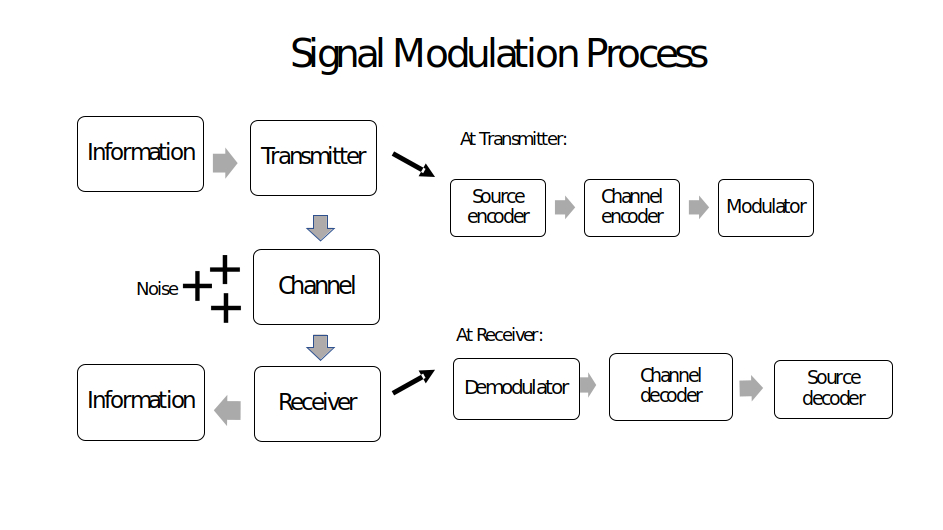
Figure 2. Signal Transmission in Wireless Channel [3]. |
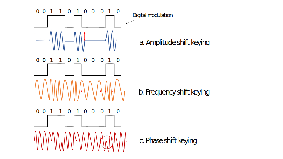
Figure 3. Different Modulation Methods. |
Quadratic Amplitude Modulation (QAM) is an analogue transmission that combines amplitudes and phase changes to achieve greater capacity [4]. An application that uses QAM is AM stereo. The purpose of QAM is to perform in a low bandwidth in order to be sustainable. The higher the QAM, the higher the data rate. However, it can't perform well with noise interference unless QAM is of lower order where it will use low bit data. The 16QAM signal is mapped out on a constellation diagram as shown in Figure 4 [5], the signal points are displayed in a square and are equally separated. If the order of modulation is increased, more points will be shown, and more bits will be transmitted. One issue with closer points is that more errors can occur since it is difficult to separate the points in the presence of noise interference [4]. The second modulation technique is Phase Shift Keying (PSK), which differs from QAM because it is an alteration of the phase in a carrier signal.
Phase Shift Keying is a form of modulation where information is transferred by changing the phase of the carrier signal. This is done by changing the sine and cosine inputs along a certain time [6]. The constellation points for a phase shift keying modulation are also equally spaced, however it is around a circle unlike the constellation in QAM as compared to Figure 4 with Figure 5. The number eight in front represents eight phases. 8PSK is considered immune to corruption because there is a great separation between each point, so it is less likely for a signal to get distracted by noise interference. The third modulation technique is known as Frequency Shift Keying (FSK).
Figure 4. 16QAM Constellation. [5]. |
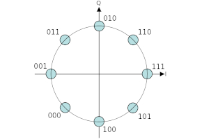
Figure 5. 8PSK Constellation. [6]. |
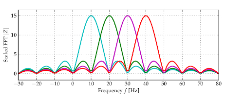
Figure 6. Image of OFDM multiple carrier signals. [8]. |
Frequency Shift Keying is a modulation where the frequency is changed. The frequency of a wave is measured by the number of times a wave passes one signal spot, within a second. OFDM is a type of Frequency shift key modulation. OFDM is Orthogonal Frequency Division Multiplexing and it uses a large number of data carriers with low bit rate data [7]. OFDM is stronger against interference and multipath effects because it has multiple modulated carriers. OFDM differs from the traditional technique of data transfer because it does not send in a series of one bit after another. The traditional format requires only one channel, making it easy for any interference to affect one frequency in that transmission [7]. In traditional data transmission, data is transferred in parallel along multiple carriers within one entire signal. OFDM uses a different approach, the data is separated in parallel sub streams with the same rate as the original stream. The sub streams use lower data rate, and the symbols are spaces far apart in time. This ensures the symbols are received efficiently without noise or data interruptions. As illustrated in Figure 6, OFDM waves are able to avoid interference with each other because when one wave peak of a signal is at its peak, all other signals are at the trough or zero. This way each signal is able to transmit data successfully in a small bandwidth because all signals overlap without disturbing each other [8].
As mentioned in Section I, in order to achieve better performance, the modulation type needs to be considered for ECC to be implemented. For example, Labrador's research team used convolution codes, where data bits are mapped in a sequence of encoder output bits. A Turbo encoder uses two convolutional codes positioned parallel to each other and are separated by an inter-leaver. A convolutional code is an error-correcting code with parity symbols [9]. The inter-leaver prevents errors from clogging by converting a transmission channel with memory into one that is memory less [10]. The researchers obtained results where that the 16QAM (modulation methods, combine with error correction code) will face more damage in the signal than compared to the 8PSK. As a conclusion they suggested OFDM as a communication channel to prevent noise spread across the bandwidth. It is suggested that OFDM will make real time acoustic communications possible but will require algorithms to prevent wideband Doppler compensation that occur underwater [1]. Another research team had a different approach as mentioned below.
Diamant's team wanted to improve performance of underwater wireless communication by achieving target bit error rate. Their solution was to use Multiple-input and multiple output (MIMO) and Code division multiple access communications system, (CDMA) [11]. Multiple- input and output is referred to using multiple antennas to increase link reliably. Code division multiple access system is enabled by multiple transmitters to send data over a channel. Their method for evaluating reliability, was through the underwater channel multipaths. They used Signal-to interference plus noise ratio (SINR), distribution parameters instead of measuring the parameters or packet error rate. They used Binary phase shift keying (BPSK) modulation, which falls into the phase shift modulation category, but it uses two phases to differentiate the binary digits [12]. BPSK is used with MIMO and CDMA communication system to demonstrate their method. The distribution parameters of SINR allowed the team to calculate precise link reliability.
Yang another researcher, studied temporal resolution of a time reversal mirror and methods for underwater communications to prevent interference in traveling data. The time reversal process will combine the multipath arrivals to reduce interference [13]. First a probe signal from the source is transferred to the vertical line array of receivers (VLA), and then it is reversed. In a vertical line array system, receivers are lined up vertically to receive one signal. After being reversed, the source us modulated using phase shift frequency and then finally transmitted into the ocean. What he had discovered is that time compressed pulse for an individual channel would usually have high level side lobes, which create inter symbol interference and bit errors. The solution Yang suggested is to use multiple receivers to prevent side lobes and phase fluctuations that will affect the received signal. BPSK signals with carrier frequencies of 3.55kHz and a bandwidth of 500 Hz were used from a shallow water environment proved high temporal furcation's can occur within minutes. However, the data also proved that the channel was coherent over a length of at least 17 seconds. Therefore, to process 17 seconds of data only one probe signal is to be used.
Another research work conducted by Behgam et al [14], compared Full tail-biting convolutional (FTBC) codes and traditional Zero tail- biting (ZTC) codes to reduce bit error rates by using a simulated channel from past years of real-world sea trail experiments. Tail-tail biting convolutional codes are used to avoid rate loss [15]. The authors decided to use this simulation technique to enable improvements in error correction codes. FTBC codes outperform ZTC codes in comparing rate loss within small messages. The research team discovered a solution to reduce packet collision rate which occurs when data sent from two stations at the same time, collide and experience a loss of performance. Their solution was to utilize a new tail biting circular MAP decoder for full tail biting convolutional (FTBC codes) for very short data blocks in underwater wireless communication. The authors compared traditional tail-biting convolutional code to full tail biting convocational codes as a result, FTBC and ZTC both achieve an acceptance bit error rate of 1% when a block length is shorter than 64% but suffer in the block code exceeds 64% due to inter symbol interference caused by multipath propagation.
In this paper, three different types of signal modulation methods and their application are introduced for better understanding of wireless communications in underwater environment. ASK, FSK, PSK are the different ways a wave is changed to achieve a signal and they are essential in performing 16QAM, 8PSK and OFDM modulations. All researchers mentioned in this paper used these modulation techniques to send signals wirelessly. However, even harnessing these modulations are not enough because as previously mentioned problems unexpectedly occur within the channel. This is where error correcting codes are implemented to detect any distortion. To improve wireless signals in a difficulty medium such as the ocean, we will need to collect underwater channel information, and carry out software simulation on data transmission using the techniques discussed within this paper. Our goal is to investigate the effectiveness of modulation and error correction codes in the underwater wireless communication system.
[1] Labrador, Y.. Modulation and Error Correction in the Underwater Acoustic Communication
Channel. International Journal of Computer Science and Network Security, VOL.9 No.7, July 2009.
[2] The benefits of Underwater Communication Systems. Available online: https://www.dspcommgen2.com/
[3] Figure 2, Information Theory Video. Can be found on YouTube: https://youtu.be/EJpxAQ_DUJ4
[4] What is QAM: Quadrature Amplitude Modulation from: https://www.electronics-notes.com/
[5] Figure 4, 16QAM, online available: http://en.wikipedia.org/wiki/16QAM
[6] What is 8PSK: Phase Shift Keying from: https://en.wikipedia.org/wiki/Phase-shift_keying#Higher-order_PSK, Figure 5, 8PSK constellation diagram, also online available: http://en.wikipedia.org/wiki/8PSK#Higher-order_PSK
[7] OFDM: Orthogonal Frequency Division Multiplexing from: https://www.electronics-notes.com
[8]Figure 6, OFDM image found online: https://dsp.stackexchange.com
[9] Error correcting code: https://www.techopedia.com
[10] Definition of Inter-leaver: https://minerva-access.unimelb.edu.au
[11] Diamant, Roee & Bucris, Yaakov & Feuer, Arie. (2016). An Efficient Method to Measure
reliability of underwater acoustic communication links. Journal of Ocean Engineering and
Science. 1. 10.1016/j.joes.2016.03.006.
[12] Binary Phase Shift Key found online: https://www.tutorialspoint.com
[13] T. C. Yang, Temporal resolutions of time-reversal and passive-phase conjugation for
underwater acoustic communications, in IEEE Journal of Oceanic Engineering,
vol. 28, no. 2, pp. 229-245, April 2003, doi: 10.1109/JOE.2003.811895.
[14] M. Behgam, Y. R. Zheng and Z. Liu, Coding for Short Messages in Multipath Underwater
Acoustic Communication Channels, OCEANS 2018 MTS/IEEE Charleston, Charleston, SC,
2018, pp. 1-5, doi: 10.1109/OCEANS.2018.8604711.
[15] Tail-biting Convolutional Coding found online: https://www.mathworks.com