
This work was done by LaGuardia student Oscar J Rivera as a part of the LaGuardia 2021-2022 CUNY Research Scholars Program (see also, CRSP). The project studies how temperature would affect a composite cantilever beam.
The project was conducted under the supervision of Dr. Yves Ngabonziza.
In this paper, the Finite Element Method (F.E.M.) is used to analyze how temperature would affect a composite cantilever beam. Using Finite Element Analysis, simulations were created to determine attributes such as normal stress and strains, thermal stress and strains, as well as displacement in the cantilever structure. With extreme heat or frigid temperatures, a given material will expand or compress creating thermal stresses and strains that may affect the integrity of the structure. Composite materials experience greater thermal stresses and strains than that of a single material. Due to this observation, composite materials of similar coefficients of thermal expansion and young’s modulus should be used to minimize stress and strain in any composite structure.
The purpose of this research is to show how the Finite Element Method (F.E.M.) is used to analyze a structure and how Finite Element Analysis (F.E.A) can process information needed to keep the integrity of said structure. There are many variables which can affect how a material reacts or functions, including but not limited to forces, vibrations, fluid flow and temperature. As a structure is exposed to these different elements, the structure may not work as intended, wear out, or ultimately fail catastrophically, possibly resulting in the injury or loss of human life. With F.E.A. we are able to analyze any materials used in a structure as an individual part or as a whole to minimize failure. Structures include but are not limited to large projects such as bridges and buildings, but also small projects such as a bike frame or car chassis. Another small but essential project is the analysis of the required screw strength to support the force exerted on it. Projects such as these make F.E.A. an essential tool for engineers to tackle different types of engineering problems.
In this paper we will be analyzing a composite cantilever beam and determine how changes in temperature will affect the structure. A cantilever beam is a beam which is supported at only one end by a fixed support. The support prevents translation in any direction and counteracts the bending moment created by a force exerted at a certain distance on the beam. Needless to say, the support should be able to withstand the weight of the structure and other forces applied to it. This is why most structures such as bridges or balconies have weight limits, as to not exceed the force which the structure can endure without failure. Although analyzing a structure can be done by hand, the advantage of using the F.E.A. feature in Solidworks is being able to simulate and analyze a structure accurately in seconds as opposed to hours or days with conventional methods. This allows us to determine how to fix the problem before it may potentially occur. However, handwritten calculations and previous knowledge is used to make sense and confirm what is outputted by the program, making it an essential part of the process.
We began with learning how to incorporate the double integration method to be able to derive an equation for the deflection of the beam which adhere to the given boundary conditions and is denoted by \(y\). The variable \(E\) pertains to the Young’s Modulus of Elasticity which has a unique value for every type of material. The variable \(I\) denotes the inertia of a certain shape or object, and also has different formulas for these different shapes which include but are not limited to rectangular or spherical objects. The variable \(L\) is related to the length of the object and lastly, \(F\) is the force exerted on such object. The deflection can be found as \begin{equation}\tag{1} y = \frac{1}{EI} \left( \frac{FL^3}{3}\right). \end{equation} The max deflection of a cantilever beam occurs at the free end. After solving the equation for the max deflection of the beam, hand calculations were verified by those of the simulation and determined the deflection to be accurate. The next step was to calculate the max stresses in the cantilever beam. In this equation, sigma denotes the stress in an object after considering the other variables. Again, inertia is denoted by \(I\), while \(c\) is considered to be the variable of the distance from the centroid or neutral axis. Lastly, \(M\) pertains to the moment or torque, which is a force applied on an object at a specific distance \begin{equation}\tag{2} \sigma = \frac{M c}{I}. \end{equation} Previous knowledge helps us determine that the max stress occurs at the fixed support. By taking the values obtained through the bending moment and moment of inertia formulas in conjunction with the distance from the centroidal or neutral axis (N.A.), the max stresses were calculated. In this case we use the formula of inertia applied for a rectangular body where \(b\) and \(h\) are the base and height of the object. Again, in the centroidal axis formula denoted by \(c\), \(h\) is also the height of the object. Thus inertia and centroidal axis are given by \begin{equation}\tag{3} I = \frac{1}{12} b h^3 \end{equation} and \begin{equation}\tag{4} c = \frac{1}{2}h. \end{equation} By writing a code through Python, hand calculations were confirmed and were found to be comparable to simulation results. Next, with the help of F.E.A. through SolidWorks, simulations were created to determine attributes such as thermal stress or strains, and displacement in each structure. The variables for strain and stress are epsilon and sigma which are applied in the x and y directions being specified by their subscripts. The coefficient of thermal expansion is represented by alpha while Poisson’s Ratio is denoted by nu. Lastly the variable of \(T\) represents the change in temperature of the object. Thermal Strain \begin{equation}\tag{5} \epsilon_x = \frac{1}{E}\left( \sigma_x - \nu \sigma_y \right) + \alpha T \end{equation} and thermal stress \begin{equation}\tag{6} \sigma_x = \frac{E}{1-\nu^2} \left(\epsilon_x + \nu \epsilon_y \right) - \frac{E \alpha T}{1-\nu}. \end{equation} Three different temperatures were used in these calculations as to show how drastic changes in temperature affected different materials. The F.E.M. works by taking an object which is created with Computer Aided Drafting (C.A.D.) and creating a mesh which breaks up the object into many small parts. As a result of the object being broken up into many small “pieces”, the program is able to analyze each part and determine attributes such as stresses and displacement in each piece simultaneously.
Figures 1 to 3 below show the strain, stress and displacement simulation profile using Solidworks for an aluminum cantilever beam subjected to a 44.42N force at the free end at 25°C.

Figure 1: Stress profile
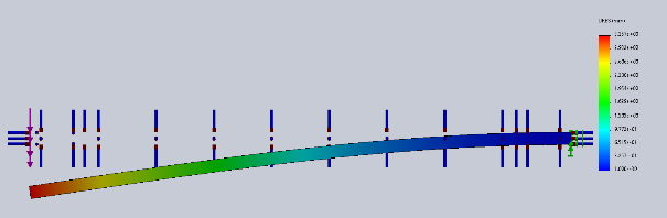
Figure 2: Displacement profile
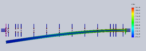
Figure 3: Strain profile
Figures 4 to 6 below show the strain, stress and displacement simulation profile using Solidworks for an aluminum cantilever beam subjected to a 44.42N force at the free end at -100°C.
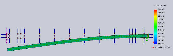
Figure 4: Stress profile
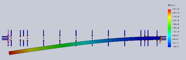
Figure 5: Displacement profile
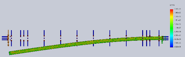
Figure 6: Strain profile
Figures 7 to 9 below show the strain, stress and displacement simulation profile using Solidworks for an aluminum cantilever beam subjected to a 44.42N force at the free end at 150°C.
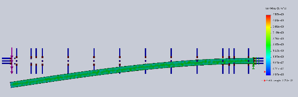
Figure 7: Stress profile

Figure 8: Displacement profile
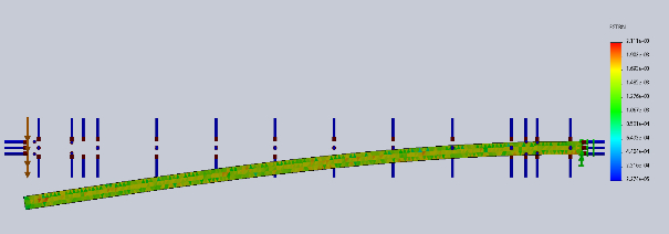
Figure 9: Strain profile
With the change in length increasing in every direction, the same force applied to the end of the beam results in a higher moment directly affecting displacements and stresses originally obtained. The same can be said for the change from room temperature to cold temperatures, except in the opposite sense. The length of the beam decreases, resulting in decreases of displacement and stresses. Although this was the case for a beam of a single material, there was a great change in thermal stresses and strains when two different materials were introduced.
Figures 10 to 12 below show the strain, stress and displacement simulation profile using Solidworks for a composite cantilever beam subjected to a 44.42N force at the free end at 25°C.

Figure 10: Stress profile
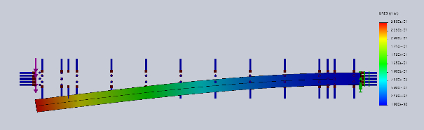
Figure 11: Displacement profile
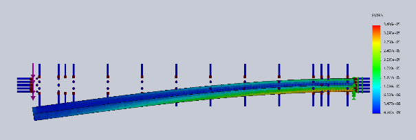
Figure 12: Strain profile
Figures 13 to 15 below show the strain, stress and displacement simulation profile using Solidworks for a composite cantilever beam subjected to a 44.42N force at the free end at -100°C.
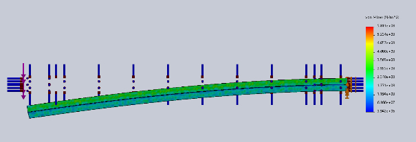
Figure 13: Stress profile
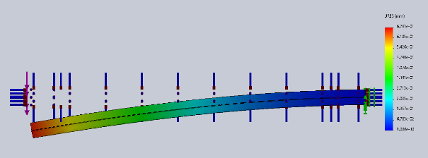
Figure 14: Displacement profile
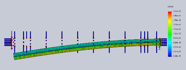
Figure 15: Strain profile
Figures 16 to 18 below show the strain, stress and displacement simulation profile using Solidworks for a composite cantilever beam subjected to a 44.42N force at the free end at 150°C.
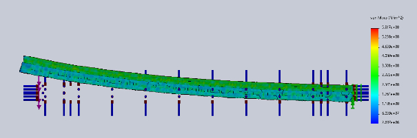
Figure 16: Stress profile
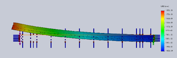
Figure 17: Displacement profile
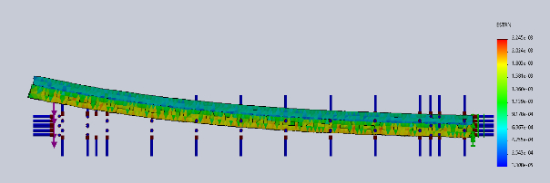
Figure 18: Strain profile
Table 1 below shows the theoretical and simulation results of stress and displacement for an aluminum cantilever beam subjected to a 44.42N force at the free end at various temperatures.
| Temperature [°C] | Stress Theory [N/m2] | Stress Simulation [N/m2] | Displacement Theory [mm] | Displacement Simulation [mm] |
|---|---|---|---|---|
| -100 | \(2.291\times10^8\) | \(2.268\times10^8\) | 3.197 | 3.202 |
| 25 | \(1.432\times10^7\) | \(1.414\times10^7\) | 3.248 | 3.257 |
| 150 | \(2.766\times10^8\) | \(2.745\times10^8\) | 3.325 | 3.334 |
To simulate these results, the same measurements for the beam were used. The length and width of the specimen were not changed, but the height was divided by two to recreate the beam with the two different materials. As was the case with temperatures, two very different materials were used to visualize results, with steel as the top layer and aluminum as the bottom. These materials were selected as aluminum’s coefficient of expansion was almost double that of steel and the strength of steel was much higher than its counterpart. While both materials of equal dimensions were subjected to the same temperature changes, the materials expanded and compressed at different rates. This resulted in changes of stress and strain in each material and very interesting results were obtained through simulations. As explored before with the single material specimen, displacement increased as temperature increased and decreased as temperature decreased. For the case of the composite beam, displacement increased both when the temperature was increased or decreased. To my surprise, when temperatures increased in the simulation, the beam curved upwards, even though there was a force pushing the end of the beam downwards. Another observation was that cracks began to form in both materials and at the bonded area as the strain due to thermal expansion was significantly greater. More cracks had appeared in the aluminum section than in the steel section since the aluminum wanted to increase in length and the steel was restricting that expansion creating more strain in the material. Another observation was that the cracks formed along the centroid of the materials and at the bonded area as strain is greatest at the centroidal axis as opposed to the surface as was the case with stress. More research was conducted on these results as they differed from expectations. To best explain this phenomenon, the concept of a thermostat was considered. Although one must set the temperature of the thermostat, bimetallic strips are what controls the heating and cooling of the system in your home. As the name suggests, bimetallic strips use two metals with different rates of expansion to achieve a certain amount of curvature in the strip. As the bimetallic strip curves due to an increase in temperature, it encounters a switch which turns off the heater as to maintain the desired temperature. As it becomes colder than that desired temperature, the curvature decreases which results in the strip no longer meeting the switch, turning the heater back on to attain the desired temperature once again. As was the case of our composite beam, it acted as a bimetallic strip, and this is what caused the displacement due to curvature. The aluminum expanded at a much higher rate than the steel, so thermal expansion forced the end of the beam upwards due to its configuration regardless of force applied. If the materials traded places, then the same curvature would happen, yet in the opposite directions.
It was concluded that with extreme heat or frigid temperatures, a given material will expand or compress creating thermal stresses and strains that may affect the integrity of the structure. While the structure analyzed will change shape, thermal stresses and strains can be directly attributed to temperature change and the thermal coefficient of expansion when there is one material present. As explored through simulations, thermal strain and stresses increase drastically when a structure with two different materials is used. This resulted in the stresses and strains in aluminum being much higher than that of steel resulting in cracks forming in the aluminum part of the structure. To minimize stresses due to temperature change, materials with similar coefficients of expansion should be used. To further this research, different combinations of materials should be explored to determine which composites optimize the durability of cantilever structures. When analyzing a problem or solution, we should consider a wide range of factors as everything is interconnected and the failure of one part can result in the failure of the whole.
I would first like to thank the directors of CRSP, as without their guidance and encouragement this opportunity for research would not have been made possible. I would further like to thank my mentor Dr. Yves Ngabonziza as he guided me through these processes and inspired me to explore different procedures to come to these conclusions. When certain conclusions were not easily attainable, he was able to explain and demonstrate how and why a course of action would be taken.
[1] Beer, F. P., Johnston, R. E., Jr, DeWolf, J. T., & Mazurek, D. F. (2014). Mechanics of Materials, 7th Edition. McGraw Hill.
[2] Hibbeler, R.C. & Kai Beng Yap. (2018). Mechanics of Materials, 10th Edition. Harlow Pearson.
[3] Pionke, C.D. & Wempner, G. (1991). The Various Approximations of the Bimetallic Thermostatic Strip. Journal of Applied Mechanics, 58(4), 1015-1020. https://doi.org/10.1115/1.2897676
[4] Budynas,R.G. (2020). Roark’s Formulas for Stress and Strain. McGraw-Hill Education.
[5] Capela, C., Costa, J.D., Ferreira, J.M. & Raimundo, A.M. (2003). Thermal Stress Analysis in Particulate Composite Components. Strain, 39(2), 49-56. https://doi.org/10.1046/j.1475-1305.2003.00053.x